Language switcher
Technical Background
Table of Content
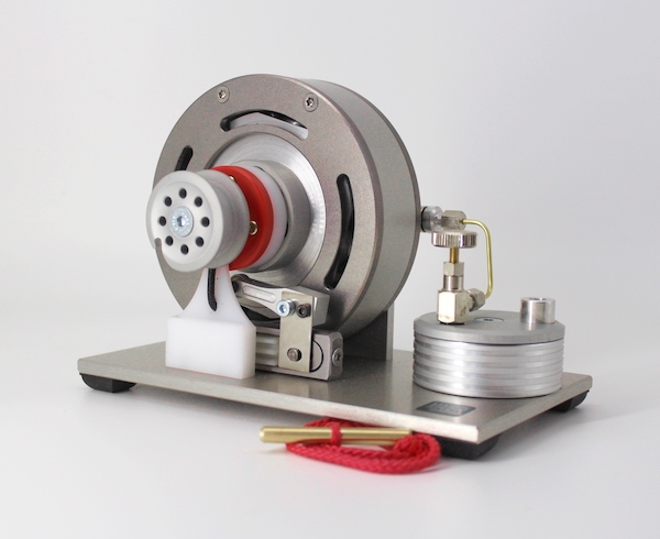
Gas Engine with pressure charged gas
Following the widespread availability of liquefied gas in cartridges, tins, bottles etc. it seemed appropriate to harness the energy a compressor yields in filling a reservoir again, as is the case with soldering irons and the like. This can also be applied to the charging of a combustion engine. Conversely, as with the normal filling cycle of combustion engines, the fuel – in this case gas – draws in ambient air and loads the engine’s cylinder capacity. A charging process e.g. via the crankcase or a piston’s induction stroke is unnecessary in a "four-stroke”. The provision of an ignitable mixture without any "personal contribution” on behalf of the engine makes for a spontaneous and easy start.
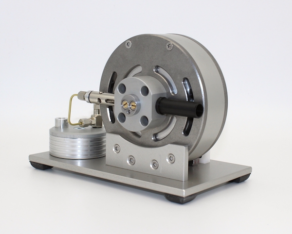
The accompanying illustrations demonstrate this engine concept.
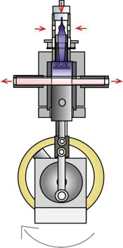 |
Fig. 1 The crankshaft of the gas engine is located at top dead centre, in other words in a charged state. The air valve, gas valve and exhaust pipes are open. Gas flows out of a fine nozzle at the head of the carburettor pipe drawing in ambient air (red arrow). A combustible mixture forms in the engine’s cylinder capacity. At the same time combusted gases are blown out through the exhaust openings. |
|---|---|
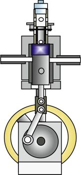 |
Fig. 2 The gas valve, air valve as well as exhaust openings are closed as a result of the upwards movement of the piston and push rod (not shown in this illustration) mounted on the crosshead of the engine. The engine is now in the compression phase. |
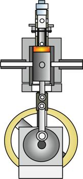 |
Fig. 3 The crankshaft has now arrived at top dead centre, the gas-air mixture is ignited by the ignition plugs. |
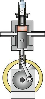 |
Fig. 4 The gas engine is now in the working phase, the piston moves down producing power after which the processes begin from the start. |
Due to the hardened piston’s crosshead guide, lateral friction force between cylinder and piston is dispensed with. Thus the engine requires only minimal lubrication in the thermally stressed region and achieves virtually odourless combustion. Depending on the type of gas used, exhaust gases are mostly water vapour. The speed and therefore the power of the engine is adjusted by the pressure of charging gas or via a gas pressure regulating valve. The gas pressure is normally between 0.5 to 2.5 bar.
Piezo High Voltage Ignition for gas engines
Piezoelectric crystals, piezo ceramics or quartz are applied in a variety ways today due to their competitive price. Their field of application ranges from quartz timers to igniters in gas lighters. Piezoelectric crystals have the capacity to respond to changes in pressure and length with changes in electrical voltage. This effect also works vice versa.
An ignition device for an internal combustion engine using a piezoelectric crystal is shown schematically in the accompanying drawing. This ignition system has the advantage that no battery is needed and, as opposed to a magneto ignition, full ignition voltage is present also at slow rotation.
The drawings show a total of one full rotation of the crankshaft, similar to the pictures of the gas engine.
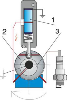 |
Fig. 5 It shows a piezoelectric crystal (1) in a metal frame. An excentric (3) mounted on the crankshaft of the engine sets the piezoelectric crystal under pressure periodically, once per revolution, with a rod and a spring. In this figure, the crankshaft is at bottom dead center, the piezoelectric crystal is thus in a relaxed state. The piezoelectric crystal also builds up a voltage when pressure drops which must be diverted to earth. This is achieved via the control gear (2) which rotates with the crankshaft. The control gear consists of an electrically insulating material in which electrically conductive connections are incorporated. |
|---|---|
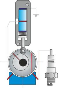 |
Fig. 6 The piezoelectric crystal is put under pressure by the crankshaft turned by the excentric and control gear. The electrical connection is now broken by the control gear. The electrical voltage in the piezoelectric crystal can not discharge and thus builds up proportionally to the pressure. |
 |
Fig. 7 The crankshaft, excentric and control gear are now at top dead centre. The control gear connects the spark plug to the piezoelectric crystal, now under tension and pressure, via the electrically conductive connection. The electrical voltage jumps over to the earthed spark plug. The engine fires the gas-air mixture. This sequence is repeated with each revolution of the crankshaft. The control wheel can be adjusted to determine exact ignition timing (early or late ignition) within certain limits, independent of the excentric. |
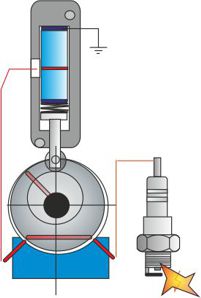 |
Fig. 8 In this position of the crankshaft the piezoelectric crystal is again mechanically relaxed. The engine fires the gas-air mixture. This sequence is repeated with each revolution of the crankshaft. |
Details of the Steam Turbine
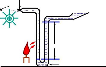 |
Fig. 9 Illustrates a vertical U-form pipe filled with water or some other liquid substance. The left part of the pipe is fitted with a nozzle at the end whereas the right part has a free opening. If heat is applied to the left vertical part of the pipe water evaporates, whereupon steam escapes through the nozzle. The maximum steam pressure achievable within this apparatus is equivalent to the weight of the depth of water in the right part of the pipe. |
|---|---|
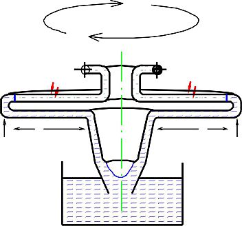 |
Fig. 10 Here the same principle is illustrated dynamically. Gravity is replaced by centrifugal force. The upper part of the now rotating apparatus is the vaporising part; fresh water flows through the lower part. The system stabilises within a broad speed range; the adjustment of heat supply can regulate rotation speed. There is a correlation between heat, rotation speed, water supply and nozzle size. |
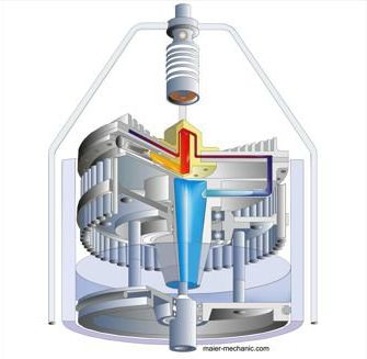 |
Fig. 11 Illustrates a technical implementation of the functional principle with a discoidal turbine. |
Opposed Piston Engine
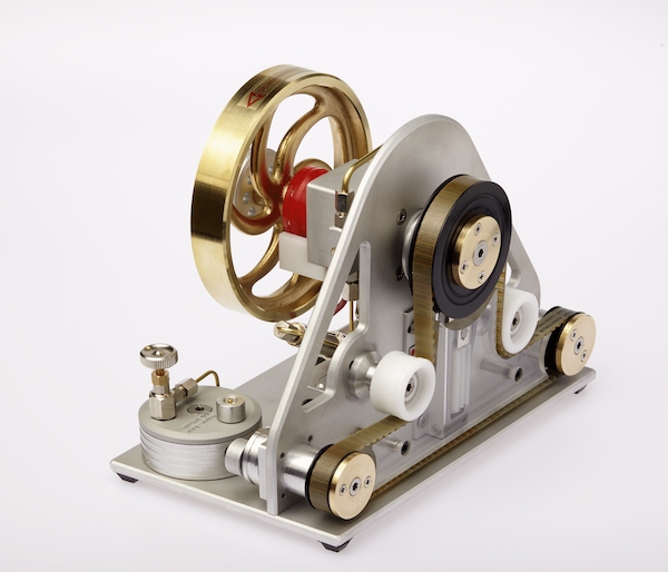
By using a sufficiently dimensioned toothed belt as the central component, it is possible to position the crankshaft, camshaft and flywheel more freely. Furthermore, there is the possibility of lower or higher gear ratios.
(This a machine translation.)
Thermal Engines
Thermal engines are available in different versions and under different names.
These are called thermo-acoustic luminescent engines etc.
Common to the various designs is that a gas column swings back and forth. The trigger for this oscillation can, for example, be heating or cooling in different sections of a tube.
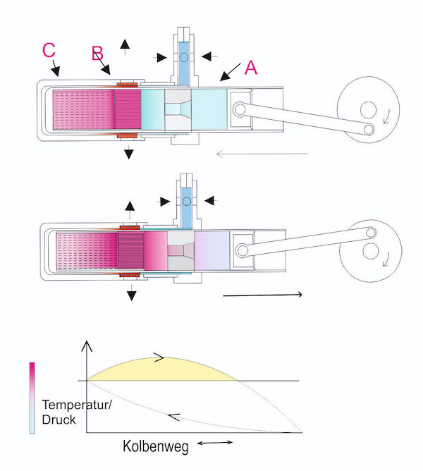
The engine described here has a gas column enclosed in a tube. The tube is divided into a cooled room A and a heated room B as well as into a buffer room C.
The gas is moved back and forth by the piston, whereby the gas (here air) heats up and cools down. In this design, the frequencies are determined by the piston and the flywheel.
To heat part B, a gas-powered catalytic converter is used, which emits its heat mainly via radiation into a glass tube containing a heat-absorbing, gas-permeable body. The gas is cooled as it flows back through a throttle into part B and through the wall of the working cylinder. See also the diagram. The drive of the engine produces further heating of the gas when returning from the buffer space C in part B.
(This a machine translation.)
Rotary Engine
The four-stroke rotary engine, consisting of a few individual parts, has neither crankshaft nor camshaft.
Rather, radially free-moving pistons are housed in a rotor. By rotating the rotor, the pistons move along the oval inner wall of the housing due to the centrifugal force.
As a result, two strokes of the pistons end up per revolution.
The first stroke is used to suck in and compress the working gases, while the following stroke is used for the expansion and ejection of the working gases.
This process is controlled by a fixed,central axis with channels and slots.
The working gas is ignited by four spark plugs in the rotor.